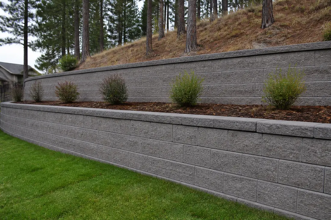
The lot slopes away from the house and the quote says two walls. Four feet at the bottom, a planting bench, four feet again above it. Two short walls instead of one eight-foot wall, and the saving is obvious before anyone explains it: smaller block, shallower excavation, less of the engineering that a tall wall drags along with it.
Terracing a slope is genuinely good practice, and the appeal is not an illusion. What is often an illusion is the arithmetic underneath it, because the tiered retaining wall offset — the horizontal distance between the back of the lower wall and the face of the upper one — is what decides whether two short walls behave like one tall one. Whether those tiers act as two independent four-foot walls or as a single eight-foot wall with a step in its face is not a matter of how they look, how they are permitted or how they are priced. It is that one dimension.
Get that distance wrong and the drawings still say four feet. The block is still four feet. What changes is underground: unless the offset clears the independence threshold in the federal design manual, the load from the upper tier runs down into the lower wall’s reinforced zone, and whether anyone accounted for it depends entirely on which analysis was performed.
On a Spokane Valley hillside lot this comes up constantly, because the ground here rarely gives you one clean grade change. It gives you a long, loose, free-draining slope that wants to be stepped. The question is where to put the step.
Why stacking two walls is the right instinct
Before the cautions, the case for it, because the reasons are real and they are not primarily about cost.
The federal design manual for this class of structure — FHWA NHI-10-024, which covers mechanically stabilized earth walls and reinforced soil slopes — recommends considering tiered walls for tall walls specifically from the standpoint of constructability. Breaking a tall wall into stacked walls of smaller height, it says, permits a fresh start with a new leveling pad, reduces vertical stress on the facing elements, and permits better control of vertical alignment of the wall face.
Those three are worth unpacking, because each one maps onto something that actually goes wrong on tall block walls.
A new leveling pad means the second tier does not inherit the first one’s errors. Any deviation from level at the base of a block wall multiplies as the courses climb, and an eight-foot wall has nowhere to correct. Reduced vertical stress on the facing matters because the facing units at the bottom of a tall wall carry everything above them. And alignment control is the reason a stepped wall usually looks better after ten years than a single tall one does.
There is a fourth benefit, and it is the one most relevant here. Depending on the offsets between the walls, the manual notes that another beneficial effect might be an overall equivalent sloped wall face, which results in lesser lateral force on the whole wall system. Stepped back far enough, two walls really are easier on the ground than one tall one.
The phrase doing the work in that sentence is depending on the offsets.
How far apart do terraced retaining walls have to be? Two thresholds
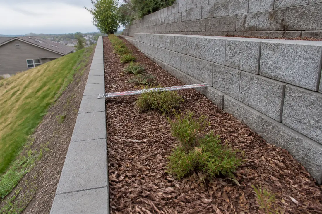
The manual’s Section 6.2 sets out the geometry using three dimensions: the height of the upper wall, H1, the height of the lower wall, H2, and the horizontal offset between them, D. Two values of D matter, and between them is a middle ground.
Where the offset is small, the pair is one wall. The manual’s rule is that for an offset at or below one twentieth of the combined height — D less than or equal to (1/20)(H1 + H2) — it is assumed that the failure surface does not fundamentally change and is simply adjusted laterally by the offset distance. The walls, it states, should be designed as a single wall with a height H, where H is the two heights added together.
Run that on the quote in front of you. Two four-foot tiers give a combined height of eight feet, and one twentieth of eight feet is 0.4 ft (4.8 in). Set the upper wall back less than 4.8 inches and the design question is no longer about two four-foot walls at all. It is an eight-foot wall that happens to have a ledge in it.
Where the offset is large, the two walls are independent. At the other end, where the offset distance D is greater than H2 multiplied by the tangent of (90 degrees minus the friction angle of the reinforced fill), the manual states the walls are not considered superimposed and are independently designed from an internal stability viewpoint. For internal stability computations in that case, the upper wall is neglected.
That formula is less forbidding than it looks once a number goes into it. For MSE walls built with fill meeting the manual’s gradation requirements, a maximum effective friction angle of 34 degrees is usually assumed, in accordance with AASHTO Article 11.10.6.2 (2007). At 34 degrees, the tangent of 56 degrees is about 1.48, so a four-foot lower wall needs an offset greater than 5.93 ft (about 5 ft 11 in) before the tiers stop being each other’s problem.
The number moves with the fill. The same passage notes that some nearly uniform fine sands meeting the specification limits may exhibit friction angles of 30 to 32 degrees. At 30 degrees the tangent of 60 degrees is about 1.73, and the required offset for that same four-foot lower wall grows to 6.93 ft (about 6 ft 11 in). A foot of extra setback, bought entirely by a property of the fill that nobody looked at.
Between those two values, you are in the intermediate case, and the manual sends the designer to its Figure 6-7a for the location of the failure surface and to Figure 6-7b for the vertical pressures to use in the internal stress calculations. No rule of thumb substitutes for working those two figures.
So the practical shape of the thing, for a pair of four-foot tiers on a typical reinforced fill: under about five inches of offset it is one eight-foot wall; over about six feet of offset it is two separate four-foot walls; and everything in between — which is to say almost every terraced wall ever built in a residential yard — is the intermediate case that requires the full analysis.
A three-foot bench between two four-foot tiers, which is a perfectly normal thing to want and looks generous standing on it, is nowhere near independence.
The two analyses a tiered wall requires
Here the manual is unusually direct, and it is the part worth carrying away from this article.
The design of superimposed walls, it says, requires two analyses. The first is a design using the simplified design rules for calculating external stability and locating the internal failure plane for internal stability. The second is a slope stability analysis, including both compound and global stability, using a reinforced soil global stability computer program. The manual describes that second analysis in four words: this is an essential computation.
Both. Not one or the other.
That matters because the first analysis is the one a block manufacturer’s design software will do, and the second generally is not. Compound and global stability ask a different question from the one wall design usually asks. Wall design asks whether the wall will slide, overturn, overstress the soil beneath it or pull the reinforcement out. Global stability asks whether the entire hillside, wall included, will rotate or slide along a surface that passes behind and beneath everything you built. A pair of walls can pass every check in the first category and fail in the second.
The companion construction volume, FHWA NHI-10-025, makes the same point from the opposite direction, and more bluntly. Listing what standard MSE wall design charts cannot be used for, its Section 10.6.1 names tiered walls outright, in the same short list as walls over 32 feet tall, sites where the slope in front of the wall is steeper than 1:3, and walls carrying soundwalls. A tiered wall is explicitly outside the range of a chart or a canned design.
So when a proposal arrives with a standard design attached, the question is not whether the design is any good. It is whether a tiered wall was ever inside its scope.
The manual also changes two specific checks for the lower wall of a pair. For external stability, the upper wall is carried as a surcharge — load type “ES” — in computing bearing pressures. And in lieu of a conventional external sliding stability computation, the designer is told to perform a wedge type slope stability analysis with failure surfaces along and exiting at the base as well as below the base, investigated at the Service I load combination with a sliding resistance factor of 0.65.
Read that again in plain terms. For the bottom wall of a terraced pair, the ordinary sliding check is not adjusted or factored up. It is replaced.
What the upper wall does to the reinforcement behind the lower one
The consequence a homeowner can actually see shows up in the reinforcement lengths, and it is the point at which a terraced job stops being cheaper than a tall one.
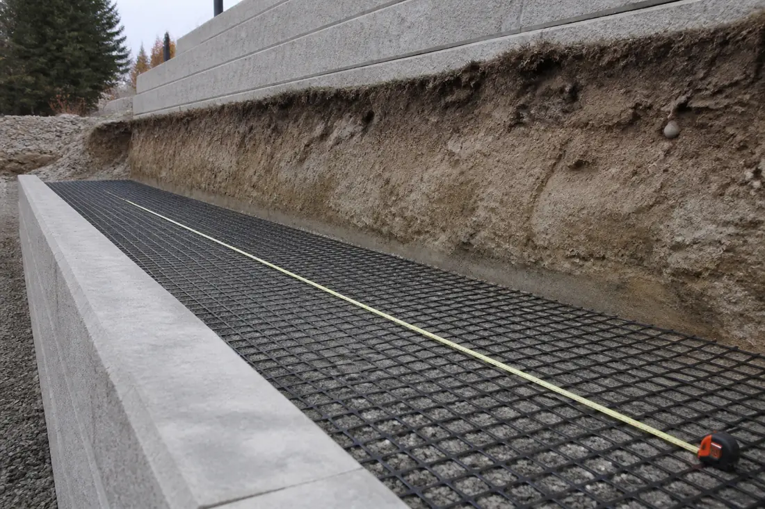
For preliminary design at offsets greater than one twentieth of the combined height, the manual gives minimum reinforcement lengths of 0.7 H1 for the upper wall and 0.6 H for the lower wall, where H is the combined height of both.
The upper wall is sized against its own height. The lower wall is not.
Take the two four-foot tiers again. The upper tier’s starting reinforcement length is 0.7 times four feet, about 2 feet 10 inches. The lower tier’s is 0.6 times the combined eight feet — about 4 feet 10 inches of grid running back into the hillside behind a wall that is four feet tall. The bottom wall is engineered against the whole slope above it, not against the four feet of soil directly behind its own face.
These are preliminary values, chosen to start the design rather than to finish it; the manual is explicit that a preliminary reinforcement length is then checked in the external and internal stability calculations, and it can come out longer. What it does not do is come out shorter because the wall was called a four-foot wall on the quote.
Pace that out in a yard and the implications land quickly. Nearly five feet of excavation behind the lower tier means the planting bench above it is sitting directly over reinforced fill. It means the two tiers are not independent construction operations that can be sequenced casually. And it frequently means the bench that made the terraced design attractive is not wide enough to hold both walls’ reinforced zones without them overlapping — which is a design question, not a field improvisation.
Our guide to what a geogrid wall assumes about the soil you put behind it covers the fill specification, compaction and connection-strength side of this, including the reinforcement length rule that applies to a single wall standing on its own.
What changes with more than two tiers?
Three and four tiers up a steep lot follow the same logic with one addition worth knowing.
The manual says the two-tier criteria can be extended to walls with more than two tiers, and that for such configurations the global and compound stability analysis becomes even more critical. For internal stability it cites findings by Wright (2005) and Leschinsky and Han (2004) that the additional vertical stress criteria may be used for walls of more than two tiers provided only the immediately overlying tier is considered to contribute to the increase in vertical stress on the lower tier.
It then adds the sequencing rule: regardless of the approach used, the analysis of tiered walls should proceed from the top wall to the bottom wall, so that the stresses are properly accumulated and accounted for in the design of the bottom-most wall. For preliminary design, the reinforcement length of the bottom-most tier can be assumed to be 0.6 times the total height of the whole wall system.
Four tiers of three feet is a twelve-foot system. The bottom three-foot wall starts its design life with roughly 7 feet 2 inches of reinforcement behind it.
Where this sits against the local permit threshold
Two separate questions get tangled here, and separating them saves arguments.
The FHWA manual is federal design guidance for transportation structures. It is not the Spokane Valley permit rule, and nothing in it tells a building department when to ask for a stamped drawing. What it describes is how a wall gets designed once somebody is designing one.
The residential code threshold is the other question — the point at which the wall stops being a landscape feature and becomes a structure requiring an engineered design. Our guide to 48 inches of unbalanced fill covers where that line sits and what sets it.
The two questions meet in an uncomfortable place for terraced walls. A pair of tiers can be configured so that each individual wall reads as modest, while the design guidance says the pair has to be analyzed as one taller structure. A proposal built around keeping each tier under a threshold has answered the permitting question and left the engineering question open.
The local ground raises the stakes on both questions. Spokane Valley sits over the Spokane Valley–Rathdrum Prairie aquifer, which the USGS describes as sand, gravel, cobbles and boulders deposited by a series of catastrophic glacial outburst floods — material coarser-grained than is typical for most basin-fill deposits. The permeability that follows is not a figure of speech. The same USGS compilation reports hydraulic conductivity estimates of about 2,600 to 6,000 ft/d for most of the aquifer on the Washington side, with about 860 ft/d in the less permeable Hillyard Trough area, and a separate study range of about 100 to 6,200 ft/d with most values above 1,000 ft/d.
Our article on the soil under a Spokane Valley retaining wall covers what that geology does to a wall. For a terraced pair the relevant part is that global stability surfaces in coarse granular ground are not shallow, and the bench between two tiers is exactly where surface water collects and goes in.
What a professional looks at, in order
An engineer or an experienced wall contractor assessing a terraced design works roughly through this sequence, and watching the order tells you whether the assessment is real.
The offset first, measured rather than estimated. Back of the lower wall to the face of the upper, not the visible width of the bench. The reinforced zone behind the lower wall extends further back than its face suggests, so the measurement that matters is not the one you can see.
The combined height, written down as a single number. If the proposal never adds the two heights together, it has not engaged with the question.
The fill, and whether anyone has tested it. The friction angle sets the independence threshold, and the difference between 34 degrees and 30 degrees is about a foot of required offset on a four-foot wall. The manual also notes that in all cases the cohesion of the reinforced fill is assumed to be zero, which is a conservative assumption deliberately — do not let anyone tell you the soil’s stickiness is helping.
Whether a global stability analysis was run at all. This is the single question that separates a designed terraced wall from two stacked landscape walls. Ask for the output, not for reassurance.
Water, at the bench. A level bench between two tiers collects surface water and delivers it to the back of the lower wall, which is the worst place for it. The construction volume’s guidance for wall plans is that surface water runoff should be collected above the wall and diverted around the wall face, and that the destination and method of termination of the internal wall drains should be detailed rather than left to the field. On a terraced pair there are two of everything, and the bench is where the upper wall’s surface water meets the lower wall’s reinforced zone. Drainage behind each tier and a graded bench that sheds rather than ponds are part of the design, not a finishing touch.
The construction sequence. Top-down analysis, bottom-up construction. The lower wall’s reinforced zone has to be complete and compacted before the upper tier’s base is cut into it.
When a lower tier is already moving
If you are reading this because the bottom wall of an existing pair is leaning or bulging, the diagnosis question is whether the wall is failing or the slope is.
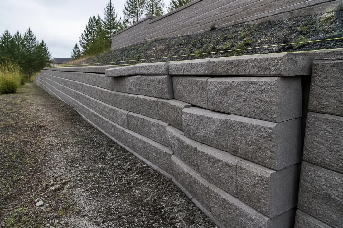
Signs that point at the wall itself include bulging concentrated in a band of courses, movement that stops at a clear vertical boundary, and block faces that have deteriorated locally. A wall problem of that kind can sometimes be addressed as a wall problem.
Signs that point at the slope include movement in the lower wall accompanied by settlement, cracking or backward tilt at the bench above it, movement that continues past the ends of the wall, and tension cracks appearing in the ground behind the upper tier. That pattern suggests a surface passing behind and beneath both walls — the compound or global failure the manual calls an essential computation — and rebuilding the lower wall to the same design would reproduce it.
The distinction matters financially, because the two conclusions have very different costs and only one of them is fixed by better block.
What drives the cost
There is no meaningful single price for a terraced wall without knowing the combined height, the offset, the fill available on site, the groundwater and drainage conditions, access for equipment, and whether an engineered design and a global stability analysis are required. The variables that move a terraced project’s cost away from a comparable single wall are specific, though:
- The lower tier’s reinforcement length, driven by combined height rather than its own, which sets excavation volume and imported fill quantity.
- Whether the bench is wide enough to keep two reinforced zones from conflicting, since the alternative is a redesign.
- The second analysis. A global and compound stability check is engineering labor that a single short wall would not have needed.
- Fill testing, because the friction angle is an input to the threshold rather than an assumption anybody should make for free.
- Access to two working levels instead of one, and the sequencing constraint that the lower tier must be finished before the upper is cut in.
- Drainage at the bench as well as behind each wall.
A terraced design can still come out cheaper than one tall wall, particularly on a long slope where a single wall would be very tall. It does not come out cheaper because the walls were described as short.
Four mistakes worth avoiding
Choosing the offset by eye, or by what looks like a nice planting bed. The bench width is a structural dimension. Picking it for the shrubs and discovering later that it put the pair in the intermediate case is a redesign, not an adjustment.
Treating the tiers as two separate projects, often a season apart. Building the lower wall one year and adding the upper one the next is common and it means the lower wall was designed and built without the surcharge it now carries. The surcharge did not exist when the wall was engineered; it exists now.
Assuming a standard design covered it. Those tools and charts do the first of the two required analyses well, and the construction volume puts tiered walls outside the scope of standard design charts altogether. The essential computation is the one they do not do.
Letting each tier’s height drive the paperwork. A pair of walls kept individually modest can still be a single taller structure as far as the design guidance is concerned. The height that matters for analysis is the combined one.
Before you buy
Ask three things before a deposit changes hands, and ask them in this order.
First, what is the offset between the tiers, and what is the combined height? Both numbers should be in the proposal already. If the proposal lists two wall heights and no offset, the geometry that decides everything else is missing.
Second, which of the three cases does this design fall into — single wall, independent walls, or intermediate? The answer should be a case plus the arithmetic that put it there, not a judgment.
Third, was a compound and global stability analysis performed, and can you see it? For any terraced pair that is not clearly in the independent case, the manual treats that analysis as essential. A contractor who has had one done will know exactly what you are asking for.
If the slope is long enough that you are choosing between one tall wall and two short ones, have that conversation before anyone prices block. The decision changes the excavation, the fill quantity, the drainage design and the engineering scope, and all four are cheaper to decide than to revise. Terracing a slope well is a good answer to a difficult lot. Terracing it to make the walls sound smaller than they are is a way of moving the cost from the quote to the repair.
This guide explains federal design guidance in plain language and is not legal or engineering advice. FHWA NHI-10-024 is design and construction guidance for transportation structures rather than a local code, and it does not replace the requirements of the authority having jurisdiction or a design prepared for your site by a licensed engineer. For a wall at or past the threshold where engineering is required, that design controls.
Sources
- FHWA NHI-10-024, Design and Construction of Mechanically Stabilized Earth Walls and Reinforced Soil Slopes, Volume I, November 2009. Section 6.2 for superimposed (tiered) MSE walls: the constructability case for tiering, including the fresh leveling pad, the reduced vertical stress on facing elements, the improved control of vertical alignment and the equivalent sloped face giving lesser lateral force; Section 6.2.1 for the two required analyses and the description of compound and global slope stability as “an essential computation”, for the preliminary minimum reinforcement lengths of 0.7 H1 for the upper wall and 0.6 H for the lower wall where H is the combined height, for the D greater than H2 tan(90 minus the friction angle) independence threshold and the neglect of the upper wall in that case, for the D at or below (1/20)(H1 + H2) single-wall case where the failure surface is assumed unchanged and shifted laterally by D, for the intermediate-offset referral to Figures 6-7a and 6-7b, and for the lower wall’s treatment of the upper wall as an “ES” surcharge in bearing with a wedge type slope stability analysis at the Service I load combination and a sliding resistance factor of 0.65 replacing the conventional sliding check; Section 6.2.2 for extension to more than two tiers, the Wright (2005) and Leschinsky and Han (2004) findings on counting only the immediately overlying tier, the top-down analysis sequence and the 0.6 times total height preliminary length for the bottom-most tier; Section 3.2 for the maximum effective friction angle of 34 degrees usually assumed per AASHTO Article 11.10.6.2 (2007), the 30 to 32 degree range for nearly uniform fine sands, the 40 degree design ceiling and the assumption of zero cohesion in the reinforced fill; and Section 4.4.3 for the statement that a preliminary reinforcement length is checked in the external and internal stability calculations.
- FHWA NHI-10-025, Design and Construction of Mechanically Stabilized Earth Walls and Reinforced Soil Slopes, Volume II, November 2009. Section 10.6.1 for the limits of standard MSEW designs, including the statement that standard design charts are not applicable where walls are tiered, where maximum wall height exceeds 32 feet (7.0 m), where slopes in front of the wall are steeper than 1:3 or for walls with soundwalls, and that soft soils or high water conditions may require a project-specific design; and for the wall plan requirements that surface water runoff should be collected above and diverted around the wall face and that the destination and method of termination of the internal wall drains be detailed.
- USGS Scientific Investigations Report 2005-5227, Compilation of Information for Spokane Valley–Rathdrum Prairie Aquifer, Washington and Idaho — Hydrologic Information. For the aquifer’s composition as sand, gravel, cobbles and boulders primarily deposited by a series of catastrophic glacial outburst floods, and as material coarser-grained than is typical for most basin-fill deposits; and for the hydraulic conductivity estimates of about 2,600 to 6,000 ft/d for most of the aquifer on the Washington side with about 860 ft/d in the less permeable Hillyard Trough area (Bolke and Vaccaro, 1981), and the range of about 100 to 6,200 ft/d with most values greater than 1,000 ft/d (CH2M HILL, 1998).