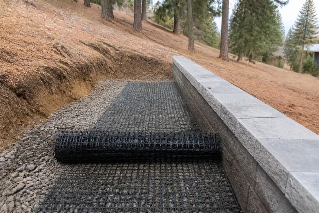
The pallets arrive and the rolls arrive with them. Somebody stands at the back of the lot, looks at a black polymer mesh that weighs almost nothing, and works out that this is the part being called engineering.
It is usually one of the smaller line items on that delivery, and it is not what holds the hillside up. What holds the hillside up is a mass of reinforced soil, and the grid only ties that mass together on the assumption that the soil inside it behaves a particular way, gets compacted a particular way, and sits against a block that was tested with that exact grid.
Change any one of those and the wall still goes up, and it still looks finished. What has changed is that the reduction factors, gradation limits and connection tests the design rested on no longer describe what was built.
The reference work for all of this is FHWA’s two-volume manual on mechanically stabilized earth walls, NHI-10-024 and NHI-10-025, published in November 2009. It is written for highway walls rather than back yards, and that gap matters in places. But it is where the numbers come from, and the numbers are more specific than most homeowners expect.
The number printed on the roll is not the number the wall is designed around
A geogrid is sold on its ultimate tensile strength, reported as the minimum average roll value. The designer does not use that figure. Volume I reduces it three times before it enters a calculation: once for damage during installation, once for creep over the design life, and once for chemical and biological degradation.
Those three factors multiply. Take the ranges the manual publishes for a polypropylene grid and do the arithmetic: creep between 4.0 and 5, installation damage between 1.10 and 1.45, durability between 1.1 and 2.0. At the favorable end of all three the combined reduction is a little under five. At the unfavorable end it is above fourteen.
Creep is the large one, and it varies by polymer. Polyester runs between 1.6 and 2.5. Polypropylene runs 4.0 to 5, and high density polyethylene 2.6 to 5. That spread is the reason two grids with the same printed strength are not interchangeable, and it comes out of laboratory creep testing that loads samples for up to 10,000 hours under ASTM D5262, or a matter of days using the stepped isothermal method of ASTM D6992. The extrapolation runs to the design life of the structure, which for a permanent wall the manual puts at 75 to 100 years.
The stone you backfill with decides how much strength survives installation
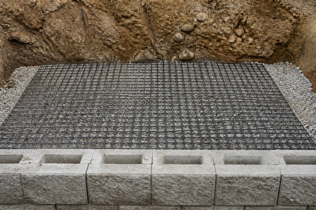
Installation damage is the factor people assume is about workmanship. It is mostly about the fill. Volume I’s Table 3-9 gives the factor for two backfills that differ only in stone size: one with a maximum particle size of four inches, one at three quarters of an inch.
For a high density polyethylene uniaxial geogrid the difference is 1.20 to 1.45 in the coarse fill against 1.10 to 1.20 in the fine. For a slit film woven polypropylene geotextile it is 1.60 to 3.00 against 1.10 to 2.00. Same product, same crew, different rock, and at the extreme two thirds of the strength is gone before the wall is finished.
The manual sets a ceiling on this. Where testing shows the factor would exceed 1.7, roughly a 40 percent strength loss, that combination of geosynthetic and backfill should not be used at all, because what remains is too variable to design around. It also sets a floor on the product: a reinforcement geotextile should weigh at least 8.0 ounces per square yard, about an AASHTO M 288 Class 1 material. Lightweight grids and fabrics are the ones that get hurt.
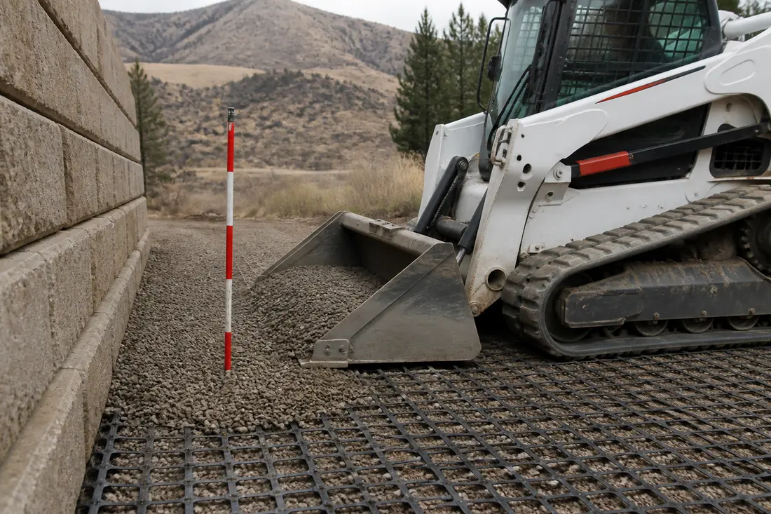
One construction detail carries real weight here. Provided at least six inches of fill sits between the grid and the wheels or tracks of the spreading equipment, the placement technique has comparatively little effect on the damage factor. Below that, it has a great deal. Equipment should not travel directly on the reinforcement, and the damage is measured by a real test, ASTM D5818, or the Washington State DOT’s own method T925, rather than estimated by eye.
Behind a reinforced wall, backfill is a specification
Volume I’s Table 3-1 states what select granular fill means for the reinforced zone. All of it passes a four inch sieve. Between zero and 60 percent passes the No. 40. No more than 15 percent passes the No. 200, which is the fines limit that does most of the work. The plasticity index is under 6. The material has to be substantially free of shale and soft particles, with a magnesium sulfate soundness loss under 30 percent after four cycles, or a sodium sulfate value under 15 percent after five.
Two further conditions sit in the footnotes and get missed. To use the manual’s default pullout values the fill needs a coefficient of uniformity of at least 4, and for geosynthetic reinforcement the maximum particle size drops to three quarters of an inch unless damage testing has been done on that specific combination.
The manual is honest that walls have been built successfully outside these limits, and that NCHRP study 24-22 found fill with up to 35 percent passing the No. 200 could be allowed safely where the material is well characterized and drainage, corrosion, deformation and pullout are all addressed in design. It is equally blunt about what goes wrong with finer, more plastic soil: significant distortion and structural failure have both been observed. Recycled asphalt is specifically not recommended, because it creeps. Crushed concrete rubble is not recommended either, because unhydrated cement produces a precipitate that clogs drains and leaves a white paste on the wall face.
Local geology is the reason this is less painful here than in many markets. The coarse glacial outwash under much of the valley is closer to a specification fill than to a problem, which is a separate subject covered in our guide to Spokane Valley soils and retaining walls. Being able to use site-won material is a genuine saving. Assuming you can, without a gradation test, is not the same thing.
Twelve inch lifts, and lighter equipment near the face
Compaction is where a specification becomes a wall. The manual calls for the reinforced fill to reach 95 to 100 percent of AASHTO T-99 maximum density, with loose lift thickness not exceeding 12 inches, and moisture held within 2 percent of optimum. It recommends being on the dry side of optimum rather than the wet side.
Within about three feet of the facing the rules change. Lighter equipment, a walk-behind plate or small roller, and thinner lifts, because heavy compaction close to the face builds lateral pressure that pushes the block out of line. Crushed stone is often used in that zone for strength and drainage, and fill is dumped at the rear and middle of the reinforcement and bladed forward toward the face rather than tipped against the block.
The grid reaches back about seven tenths of the wall height
This is the number that changes what a project costs, and it surprises people. Reinforcement length starts at the greater of 0.7 times the design height or eight feet. For a six foot wall that is eight feet of grid running back from the face, which means eight feet of excavation, eight feet of specified fill, and eight feet of ground that cannot hold anything else.
Walls carrying a sloping surcharge or a concentrated load generally need more, often 0.8 to 1.1 times the height. The eight foot floor exists to suit transportation scale compaction equipment; AASHTO’s 2007 commentary allows six feet for short walls where smaller equipment is used and the other design requirements are met, and the manual notes that shorter minimum is generally for landscape walls not supporting traffic. The 0.7 ratio itself still holds.
The manual also recommends extending the top two layers three feet beyond the rest where post-construction movement has been seen on similar projects, or where seismic loading could open tension cracks in the backfill behind the reinforced zone.
A tight lot is where this bites. If the property line, a driveway or a pool sits six feet behind a wall that wants eight, the reinforced option is not available at that height, and the honest answers are a shorter wall, a terrace, or a different structure. That decision belongs in design and permitting before anything is ordered.
A reinforced wall is designed to move
Most of the movement happens during construction, and the manual gives rough figures for it at a reinforcement length of 0.7 times the height: about three quarters of an inch per 10 feet of wall height for inextensible steel reinforcement, about an inch per 10 feet for geogrid, and about an inch and a half per 10 feet for geotextile. The order is the point. The more extensible the reinforcement, the more the face moves to mobilize it. The manual presents these as a guide rather than a prediction, and notes that actual displacement depends on soil, compaction effort and the contractor.
Two things follow. Reinforcement length buys tolerance: going from the theoretical lower limit of 0.5 times the height to 0.7 cuts the expected deformation roughly in half. And surcharge costs tolerance, with relative displacement on a 20 foot wall increasing by about 25 percent for every 400 pounds per square foot added above it.
Face movement during construction is expected and has a published order of magnitude. Movement that is still measurable long after the wall was finished is a different question, and the things to look at are surcharge, settlement and drainage rather than an assumption that the wall is settling in.
The block and the grid are a tested pair
Segmental block units are dry-stacked in running bond, their cores filled with aggregate, with shear pins, lips or keys between courses. The grid is held by friction, by a mechanical connection, or by both. Unlike precast panel walls there are no bearing pads, so the connection and the compaction have to absorb the elastic compression of the fill.
Volume I is unambiguous about what that means for procurement. Connection strength varies with unit geometry, batter, normal pressure, unit depth and core infill, so it is specific to each unit and reinforcement combination and has to be developed uniquely by test for that combination.
Read plainly: the grid and the block are one approved assembly. Substituting another manufacturer’s grid of the same rated strength, or another block of the same size, leaves the connection untested even though both products are sound. Both items look generic on a delivery ticket, which is what makes the substitution easy to miss. It is worth asking about on any block and segmental wall installation before the order is placed.
Two related points from the same chapter. Polyester grids and geotextiles should not be cast into concrete, because of chemical degradation. And where polyethylene grid is cast into a panel and joined with a bodkin, the slack has to be taken out during construction, or the connection does nothing until the wall has already moved.
In this climate the block itself is a specification
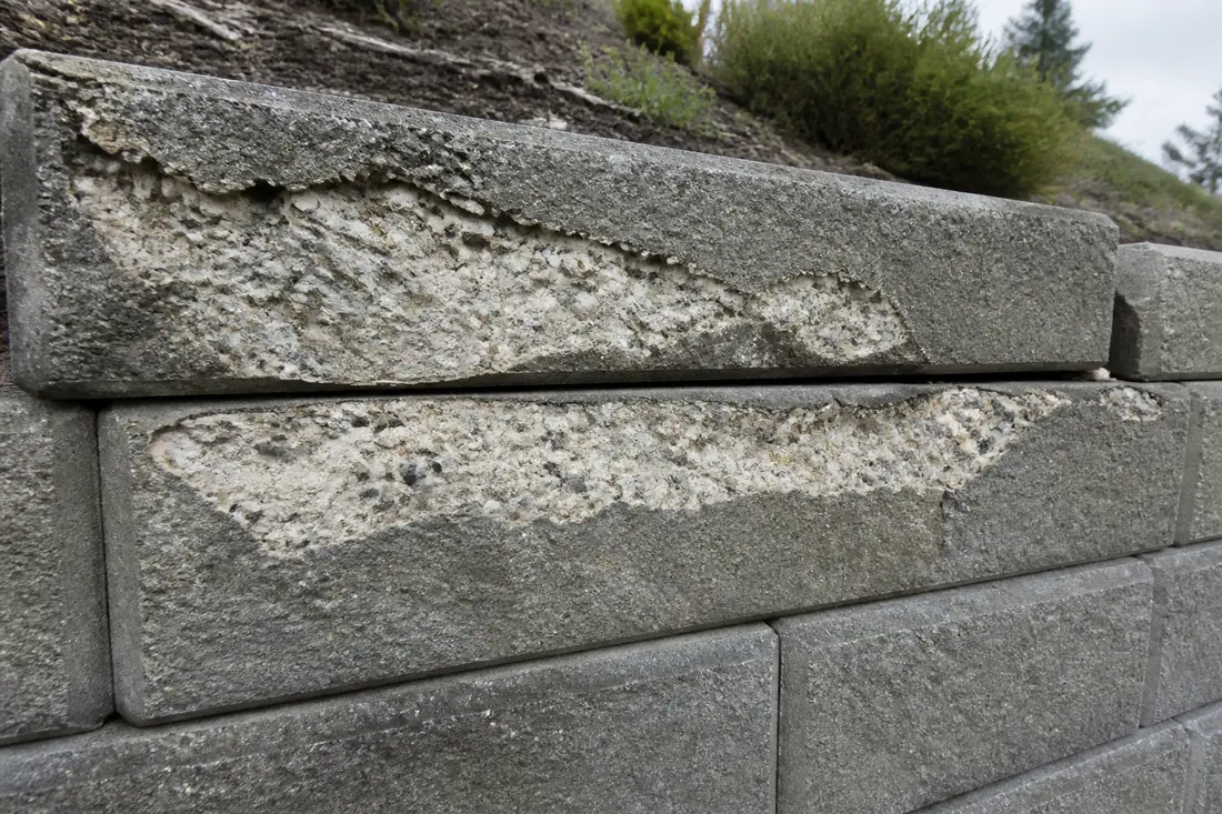
Dry-cast block is vulnerable to freeze-thaw damage, particularly with de-icing salt, and the manual says so directly about northern tier states. ASTM C1372 is the standard specification for segmental retaining wall units, and the manual treats it as a model to be tightened rather than a sufficient answer: compressive strength raised to 4,000 psi, maximum water absorption capped at 5 percent, and freeze-thaw testing requirements modified.
Volume II’s Chapter 10 puts that into specification language. At delivery, modular block facing units should meet 4,000 psi as the average of three coupons and 3,500 psi for any individual coupon, a minimum oven dry unit weight of 125 pounds per cubic foot, and maximum water absorption of 5 percent after 24 hours, tested under ASTM C140 on lots of no more than 2,000 blocks.
Where repeated freezing and thawing under saturated conditions occurs, units are tested to ASTM C1262 on five specimens, from the same mix design and process, run not more than 18 months before delivery. The acceptance criteria are either a weight loss under 1 percent for four of five specimens after 150 cycles in water, or under 1.5 percent for four of five after 50 cycles in a 3 percent saline solution. Minnesota DOT, which has both the winters and the salt, goes further still: coupon strengths of 5,500 psi minimum and 5,800 psi averaged over three units, no more than 1 percent mean weight loss at 90 cycles in saline, and separate, tighter cycle counts for cap units, which are the most exposed pieces on the wall. Its cap detail calls for the top surface to fall an inch over ten inches, front to back or crowned, so water leaves rather than stands.
The practical catch is timing. C1262 testing takes more than three months, so it cannot be run per project. The manual’s conclusion is that it belongs to an agency’s approved products list, decided long before a job starts. For a homeowner the equivalent question is whether the manufacturer holds current freeze-thaw test data for the specific unit, and what the result was.
What gets looked at, in the order it happens
Volume II’s inspection chapter is a useful read for anyone paying for a wall, because it sets out the sequence. Material submittals and approvals come first, then the construction sequence for the reinforcement system, then the site: foundation preparation, leveling pad level and alignment, excavation limits, dewatering, and drainage features including seeps and nearby water.
Facing units get rejected for compressive strength below specification, molding defects, honeycombing, severe cracking or spalling, finish color variation, dimensional tolerance and misaligned connections. Tolerances are tight; overall block dimensions within an eighth of an inch and course height within a sixteenth.
Then the reinforcement, and this is the step worth knowing about. Labels are checked against the certification documents, because product styles look alike and have different properties. Samples are weighed in the field and compared against the manufacturer’s stated mass per unit area, and sent for laboratory verification. Roll ends get color coded where more than one style is in use, so the wrong grid does not end up in the wrong course. And where possible the grid is checked after fill placement, by uncovering a small section early in the job to see what the compaction actually did to it.
What drives the cost
There is no useful single price for a reinforced wall without knowing the design height, what sits above it, and what the fill situation is. Those three move the number more than anything else.
- Excavation depth behind the face. At 0.7 times the height, a taller wall takes back a disproportionate amount of yard, and that is dig, haul and restoration.
- Whether site soil can be the reinforced fill. Passing gradation and plasticity means a fraction of the material cost of importing. Failing it means exporting the native soil and importing specification fill, twice the trucking.
- Surcharge above the wall. A driveway, a slope or a structure pushes reinforcement length toward 0.8 to 1.1 times the height and tightens everything else.
- Block grade. A unit with current freeze-thaw data at a higher strength and lower absorption costs more per square foot and is the wrong place to save in a climate with both frost and road salt.
- Compaction access near the face. The three foot zone that needs small equipment is slow, and slow is labor.
- Drainage. Specification fill is not the same as free draining, as the manual notes about granular fill carrying even a few percent fines. Drainage gets designed separately; see retaining wall drainage.
Common mistakes
Treating the grid as the product and the fill as a detail. The grid’s contribution is already discounted three times before design. The fill is not discounted at all; it either meets the specification or the design does not describe the wall that got built.
Mixing a block from one system with a grid from another. Connection strength exists only for combinations that were tested together. Two sound products can make an untested connection.
Running the loader straight over the grid. Six inches of cover between reinforcement and tracks is the difference between a modest damage factor and one the manual says disqualifies the combination.
Compacting hard against the face. It looks like diligence and it pushes courses out of alignment, which is why the manual specifies lighter equipment within three feet.
Buying wall block on appearance in a freeze-thaw climate. Absorption and freeze-thaw cycles are measurable properties that two visually identical units can differ on, and the test takes a quarter of a year, so it is never done for your job specifically.
Before you buy
Ask the contractor for three documents before a deposit changes hands: the design or manufacturer’s engineering for the specific wall height and surcharge, a gradation and plasticity result for the fill that will go in the reinforced zone, and the connection strength data for that block with that grid. All three exist for any wall designed to the FHWA or AASHTO approach. A proposal that cannot produce them is describing a landscape wall, which may be entirely appropriate at a modest height and is a different structure with different expectations.
Then ask what reinforcement length the design uses and pace it out in the yard. If the answer is shorter than 0.7 times the finished height, there should be a reason stated in writing. Where the wall is tall enough or loaded enough that the code pushes it into engineered territory, our guide to 48 inches of unbalanced fill covers where that line sits locally.
The sequence that saves money is unglamorous: test the soil before designing the wall, design the wall before pricing the block, and buy the block and the grid as one tested assembly. Taken in that order, each step produces the information the next one needs. Taken out of order, each step commits money to an assumption that has not been checked yet.
FHWA NHI-10-024 and NHI-10-025 are federal design and construction guidance for transportation structures, not a local code, and they do not replace the requirements of the authority having jurisdiction or a design prepared for your site by a licensed engineer. For a wall at or past the threshold where engineering is required, that design controls.
Sources
- FHWA NHI-10-024, Design and Construction of Mechanically Stabilized Earth Walls and Reinforced Soil Slopes, Volume I, November 2009. Table 3-1 for the select granular reinforced fill gradation, the plasticity index under 6 and the magnesium and sodium sulfate soundness limits, with its footnotes on the coefficient of uniformity and the three-quarter-inch maximum particle size for geosynthetics; Section 3.2 for the marginal fill discussion, the NCHRP 24-22 finding at 35 percent passing the No. 200, the recycled asphalt and crushed concrete cautions, the compaction moisture tolerance and the lighter compaction zone within three feet of the face; Section 2.5 for 95 to 100 percent of AASHTO T-99 and the 12-inch loose lift; Section 3.5.2 for the long-term design strength expression and the installation damage, creep and durability reduction factors, including Table 3-9, the 1.7 installation damage ceiling, the six inches of cover over the reinforcement, the 8.0 ounce per square yard minimum geotextile weight, the creep ranges by polymer and the ASTM D5262, D6992, D5818 and WSDOT T925 test methods; Section 3.6.2 for ASTM C1372 as a model specification at 4,000 psi and 5 percent absorption, the ASTM C1262 testing duration and Table 3-14 for the Minnesota DOT cold weather criteria; Section 4.4.3 for the reinforcement length at the greater of 0.7H or eight feet, the 0.8H to 1.1H surcharge case, the AASHTO C.11.10.2.1 six-foot allowance and the extended top two layers; Section 4.4.7.i for the statement that modular block connection strength must be developed uniquely by test for each unit and reinforcement combination, and for the polyester and bodkin connection cautions; and Figure 2-15 for the lateral displacement estimates at a reinforcement length of 0.7H and the surcharge effect.
- FHWA NHI-10-025, Design and Construction of Mechanically Stabilized Earth Walls and Reinforced Soil Slopes, Volume II, November 2009. Chapter 10 for the modular block facing unit physical requirements at delivery (4,000 psi as the average of three coupons, 3,500 psi individual, 125 pounds per cubic foot minimum oven dry unit weight, 5 percent maximum absorption after 24 hours, ASTM C140 testing on lots of no more than 2,000 blocks) and for the ASTM C1262 freeze-thaw acceptance criteria, the five specimens, the 18-month limit before delivery and the 150-cycle water and 50-cycle saline alternatives; Chapter 11 for the field inspection sequence, the grounds for rejecting facing units, the dimensional tolerances and the instruction to weigh reinforcement samples in the field against the manufacturer’s stated mass per unit area.